181 Fremont Makes Cover of Foundation Drilling Magazine
Source: Foundation Drilling Magazine

COVER FEATURE: Malcolm and 181 Fremont Tower
By Peter Faust, Vice President Business Development, Malcolm Drilling Company, Inc
The 181 Fremont Tower
The 181 FremontTower is a new build mixed-use tower, currently under construction in the dense urban core of the South Market District of San Francisco, California. This high-rise will consist of 54 above ground floors with the roof level 700 feet high. Atop the roof will be architectural features including a spire that will top out at just over 800 feet, which will make it the second tallest building in San Francisco upon completion.
The tower boasts a unique architectural and structural approach, using exterior mega-cross braces which provide the lateral stability of the tower during seismic and wind loading. The mega cross-braces can be seen in the architectural rendering in Figure 1 (a & b). This approach allows for a more open floor plate as compared to the more common reinforced concrete core approach, which is critical for this building because of the small and narrow site. However, this structural approach creates a chal lenge for the foundations because the seismic loads are concentrated in the Franciscan Complex bedrock were framed into a ring beam pile cap that encompasses the entire perimeter of the building.
Below the tower will be a 5 level basement, extending 60 feet below existing grade, which houses a loading dock facility and underground parking. A watertight, stiff temporary shoring system was required to allow the excavation to be performed without adversely affecting adjacent improve ments, including a 27 floor tower to the east and a three-story masonry building to the south. The shoring wall along the north side of the excavation is shared with another deep excavation under construction simultane ously for the Transbay Transit Center.
Site Soils and Rock
The site lies near the eastern margin of San Francisco Bay. Consequently, the site soils are sequences of sands and clays which correspond to the fluctuating depositional changes of the bay margin. Figure 2 shows a typical cone penetration test (CPT) result and an in-situ shear wave velocity test (suspension logging method) juxtaposed with the simplified site stratigraphy.
Fill is found at the ground surface which is underlain by a seemingly random sequence of Holocene marine clays and sands. Below these interbed ded marine deposits lies a stiff, late Pleistocene marine clay referred to locally as Old Bay Clay, which is relatively homogeneous and slightly over consolidated. Beneath the Old Bay Clay is a very stiff clay with interbedded sands and gravels that are terrestrial, colluvial, fluvial, and possibly estuar ine in origin referred to locally as Valley Deposits. This material has been found to have cobbles and large pieces of wood.
The bedrock underlying the site soils is the Franciscan Complex, which consists of mainly sandstones, siltstones, and shale based rock types. Blocks of more competent material are floating in a heavily sheared matrix. These harder blocks and softer matrix are chaotically arranged with adds complexity to the design and construction of the drilled shafts which were embedded in this material.
Foundations: Design of the Foundation System
Under gravity, most of the vertical building load is resisted by 34 drilled shafts located along the perimeter of the building. Some of the vertical load is also resisted by hydrostatic uplift on the 3 foot thick base mat and through columns framing into nine drilled shafts in the middle of the building. The design does not rely on forces transferred directly to the medium stiff Bay Mud underlying the base mat.
During wind or seismic loading, most of the lateral forces of the superstructure are resisted by the diagonal megabraces which then must be re sisted by columns which land in the six corners of the basement. The maximum axial force that falls on one of these columns in the Maximum Considered Earthquake (MCE) event is too large to be resisted by a single foundation element. The structural engineer first considered using conven tional pile caps in the corners of the building to transfer the load between several shafts; however, the loading on these caps would be highly eccen tric due to the proximity of the property boundary. Furthermore, each additional shaft would need to be located further away from the location of the corner loads, making these additional shafts less efficient. The solution was to tie II of the perimeter shafts together through a 12 foot deep by 8 foot wide ring beam pile cap as indicated in Figure 3
Design of the Drilled Shafts
The deep foundation consists of 5 and 6 foot diameter shafts. The tip depth of each shaft was selected to achieve the required ultimate capacity based on the stratigraphy local to the shaft. Although the plan area of the site is small, the depth to bedrock, shown in Figure 3, varies by as much as 14 feet between the east and west ends of the site. The deepest shaft drilled was slightly over 260 feet from the ground surface. The longest rock socket is over 25 feet in length.
Not only do the bedrock contours vary widely across the site, but the composition and, therefore, the capacity of the Franciscan Complex is very chaotic. This is a reflection of the violent geological activity of the past and (unfortunately) the present in and around the city of San Francisco. Little was known about the load carrying capacity of this chaotic formation since only a few full-scale load tests have ever been performed in this material. Unfortunately, all of these tests were on drilled shafts installed with different drilling methods. The project team therefore decided to install one Osterberg bi-directional load cell (O-cell) in a test shaft to assist in the foundation design.
The test shaft was designed to be incorporated into the final foundation system to reduce overall cost. The 6 foot diameter shaft was socketed 30 feet into the bedrock with the O cells located 20 feet above the shaft base. Using three 24 inch O-cells on a single plane, an equivalent top down load of 14,000 kips was applied by Loadtest. The shaft displacements, strain gage and load data were analyzed to obtain q-z curves for the shaft bottom and t-z curves in 16 zones along the sides. The t-z curves within the Franciscan Complex revealed more than 20 ksf mobilized unit side shear. These high values were unexpected and are attributed to the selected construction technique with extreme focus on shaft cleanliness during the drilling and concreting process. They allowed for an optimized shaft-by-shaft design based on rock conditions and actual load demand.
Construction of the Drilled Shafts
The deep foundation system design required drilling to depths beyond the reach of conventional large diameter rotary drilling equipment. Malcolm’s Bauer BG46 rig with an 80 meter long Kelly bar was used to drill each shaft from existing site grade using drilling buckets and augers. Since the overburden soil layers consisted of loose man-made fill, including old wooden piles, and several sand lenses to depths around 80 feet, Malcolm elected to install temporary steel casing to stabilize these layers. Drilling beyond the casing in the mostly stiff clay layers proceeded under polymer slurry support. The Valley Deposits were believed to pose a significant borehole stability risk due to their loose matrix of gravel and cobble components; therefore, Malcolm decided to use the higher grade KB* polymer product family which allows for immediate slurry enhancement with stabilizing additives when loose soil layers are encountered. Upon completion of the excavation of the shafts, airlifting was used to clean the tip.
The shafts were completed ahead of schedule and no anomalies were revealed by the integrity testing via Crosshole Sonic Logging (CSL). The success of the drilled shaft installation at 181 Fremont is attributable to the close collaboration between the engineers, the general contractor [Level 10 Construction], and specialty foundation contractor as well as the focus on shaft clean liness until shortly before the concrete pour.
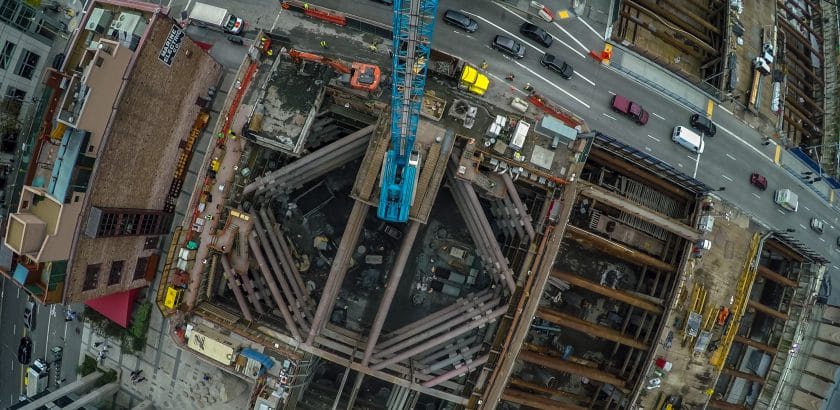
Shoring and Excavation: Design and Construction of the Excavation Support System
Figure5 shows the as-built shoring system with the excavation at full depth. The 60 foot deep excavation is supported by soil mix shoring walls and an internal bracing system comprised of four bracing levels. Figure 6 presents a plan view of bracing system. As discussed below, design and construction of the shoring system successfully navigated several site constraints in order to ensure the constructability of the bracing system and the ability to perform the excavation in an efficient manner.
As noted above, the north side of the basement excavation utilized the CDSM wall with embedded soldier piles constructed for the TTC excavation. New 3.3 foot thick cutter soil mix (CSM) shoring walls reinforced with W30 steel piles were used to shore the west, east and south sides of the excavation. CSM differs from CDSM in that it employs two sets of counter-rotating, vertically mounted cutter wheels to form rectangular soil-cement panels (as opposed to circular secant shafts). The soil mix shoring walls were designed to act as both a stiff structural wall as well as to provide groundwater cutoff. Mixing extended to a depth of 5 feet below existing grade in order to penetrate into the low permeability Old Bay Clay for bottom cutoff.
The shoring system was designed to be sufficiently stiff to minimize movement of the adjacent TTC shoring system and to protect the 199 Fremont and Marine Electric buildings against excessive movement. Special bracing details were employed at the shared TTC shoring wall to have a means of controlling the response of the TTC shoring to the 181 Fremont excavation.
Performance Criteria and Monitoring
The design criteria limited horizontal deflection of the CDSM wall to 1.o inches above the top level of bracing and 1.5 inches below the top level of bracing. Compliance with these criteria were assessed by Arup via monitoring of approximately 40 glass prism survey monuments mounted to the tops of the soldier piles in the soil mix walls and 6 inclinometers embedded in the soil mix walls and extending to bedrock. The survey data was made accessible to the contractors, engineers, adjacent property owners and other stakeholders through an online portal managed by Arup known as the Global Analyzer. The inclinometers were read manually at roughly two week intervals and interpretation of the data was calibrated against deflections measured at nearby survey monuments.
The design criteria also required that dewatering within the excavation footprint not lower the groundwater more than 5 feet outside the excavation. Compliance with this criterion was assessed via manual reading of piezometers in stalled in 2 boreholes: one adjacent to the soil mix wall along Fremont Street and the other adjacent to the soil mix walls near the truncated southeast corner. Two nested piezometers were installed in each borehole that were slotted within the fill and marine sand layers.
Summary and Conclusions
While challenging, this project demonstrated that very deep shafts can be constructed on a very small construction site right in downtown San Francisco. In addition, results from a full-scale load test, using the Osterberg cell method, provided unique data on the frictional capacity of the deep soil and Franciscan Complex bedrock in the region.
Design and construction of the shoring system was complicated by the adjacent Transbay Transit Center excavation as well as the busy roadway and the adjacent buildings, 199 Fremont and the Marine Electric Building. To allow for flexibility during construction, hydraulic rams were placed in a transfer waler along the shared TTC shoring wall that could adjust the forces transferred through to the TTC excavation if required.
Such a tight and complex project site requires very close collaboration between the owner, designer, general contractor, and specialty foundation and shoring subcontractor to make it successful. Detailed planning and extra effort up-front (soil investigation, obstruction removal, work sequence, contingency plans) benefits the construction schedule and overall cost. Furthermore, this project demonstrates that the specialty foundation and shoring subcontractor can play a vital role in the decision about the most time and cost effective construction techniques when consulted ahead of time and not only after things go wrong.
Project Team:
Owner: Jay Paul Company, San Francisco, CA
General Contractor: Level 10 Construction, Sunnyvale, CA
Specialty Contractor: Malcolm Drilling Co.*, San Francisco, CA
Civil and Geotechnical Engineer: Arup, San Francisco, CA
Shoring Designer: Brierley Associates, Moraga, CA
Link to Original Article (may require registration)
http://bit.ly/2fP76pW ![]()